This is an old revision of the document!
Moodlamp Build Instructions
This page will contain all instructions for building a moodlamp version 0.30 including pictures of the whole process.
wrong Partlist at Easterhegg 2010
The Kit's from Easterhegg 2010, were shiped with the wrong part list (small dinA6 letter):
- the color Codes are outdated, use the codes on this site
- 220 ohm replaces 180 ohm
Farbcode der Widerstände und Kondensatoren in Kit Revision 4
| part | value | model | colorcode |
|---|---|---|---|
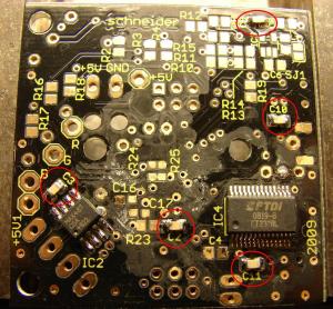
| C[16,17] | 100nF | 0603 | yellow |
| C[1,2,3,9,10,11,13] | 100nF | 0805 | red |
| C[4,5] | 22pF | 0805 | blue |
| R[1,9,19] | 10kΩ | 0805 | black |
| R25 | 10kΩ | 0603 | green |
| R[2,3,4,8] | 100kΩ | 0805 | brown |
| R[20,21,22] | 220Ω | 0603 | grey/pencil |
| R24 | 22kΩ | 0603 | pink |
Tools You Need
You will need a variety of tool to build a moodlamp:
- soldering iron
- fine tip and a bigger tip
- flux
- solder
- solder wick
- tweezers
- wire cutter
- vise
- insulation tape
Soldering SMD parts
Most parts of the moodlamp are surface mounted. See http://www.spida.net/projects/hardware/smd-soldering/ for an introduction. (TODO: insert english page here)
Step 1: Populating the big chips
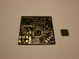
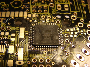
The first step is to populate the IC1 and IC4, the microcontroller(the brain) and the usb interface(optional).
These chips have many pins and there are three basic methods for soldering them:
- Use a fine tip and solder each pin separately
- Use a bigger tip, solder all pins at once and remove the excessive solder with the solder wick.
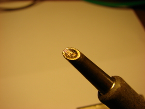
- Use a special tip, a Concave soldering iron tip, which contains a little cavity for solder by surface tension.
We recommend and describe the later method as it produces the best result. If you don't have one of these special tips for your soldering iron the next best method is using the big tip.
Step 1.1:
Step 1.2:
Step 1.3:
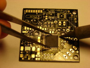
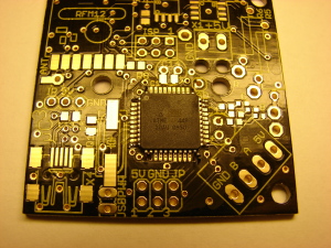
Position IC1 and solder one pin to the pad of the previous step. Make sure the IC is positioned correctly: The circle in one corner
of the chip has to be in the same corner on the pcb.
(IC1 might be taped to the PCB)
Step 1.4:
Step 1.5:
Step 1.6:
Step 1.7:
Move the tip containing the solder along one side of the chip. There will be only solder left on the pins without connecting them. If the result has shorts you can again add some flux and try again. Small shorts at the edges can also be removed with solder tip. I've made a little video showing the process:
Step 1.8:
Step 1.9:
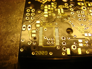
pads of IC1 and IC4 without connection
If you unsolder IC1 or IC4 for whatever reason you may destroy pads, especially those without connection.
These pads are unused, it is no Problem if you loose them. They are marked blue in the following pictures.
Step 2: Populating the other chips
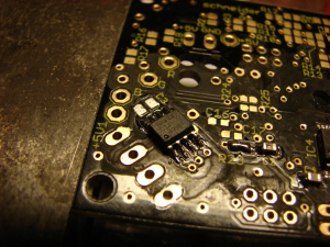
Parts used: MAX487(IC2), IRF7103(T1, T2)
From here on a small solder tip is used. A diameter of about 0.8mm will do just fine.
Start with transistor T2 on the top side. The drawings on the pcb mark the orientation of the chip.
Step 2.1:
Step 2.2:
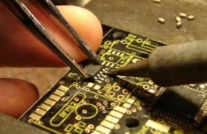
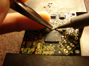
Use the tweezers in one hand to position the chip on the pads and the soldering iron to heat the pad containing the solder:
Step 2.3:
Now solder every pin of the chip to the pcb. The pins have enough space between them to solder the separately.
Step 2.4:
Step 3: Populating the resistors and capacitors
The small surface mounted resistors and capacitors come in two different sizes: 0805 and 0603. This number describes the size of the sides of the part in .001-inch. To make it short: the 0805 parts are the bigger ones.
To solder these parts add solder to one of the pads and add the part with tweezers afterwards.
Tip: If one of the pads has many copper traces attached add solder to the pad that has less copper traces attached. This pad will be easier to heat and make the process more smooth. The following picture shows the preferred pads for R2, R3 and R4. The right side has 3 traces going into the solid ground plane:
Step 3.1:
Step 3.2:
Step 3.3:
Step 3.4:
Step 3.5:
Step 3.6:
Step 3.6:
Step 3.7:
Step 3.9:
Step 3.8:
Step 3.8:
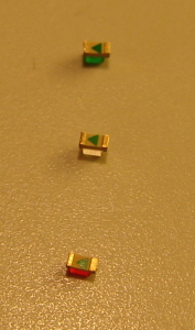
Parts used: 3 x LED in 0603 (LED1, LED2, LED3)
These are some status leds you can add to your moodlamp:
The leds are red, green and blue. The blue one has a transparent lens. At the bottom side of the leds is a small arrow. This arrow points to the cathode of the led. This is the “negative” terminal:
Solder the leds to the pcb so that this arrow points away from the big chip in the middle:
Step 4: Mounting the bigger components, solder bridges and connectors
Step 4.1:
Parts used: 1 x mini usb jack (X4)
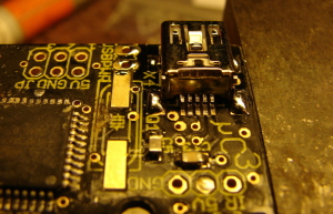
When mounting the usb jack take special care that all pins are connected to the pads and that no pins have shorts. Use solder wick if necessary:
Step 4.1:
Step 4.2:
Parts used: 1 x RFM12 rf module
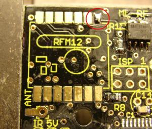
Add solder to one pad:
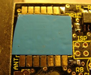
Use some tape to insulate the pcb from the module to prevent shorts that might occur from the two pcbs touching:
Solder the module to the pcb like a normal chip:
Step 4.3:
Parts used: none
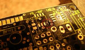
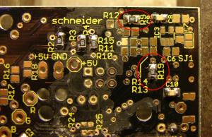
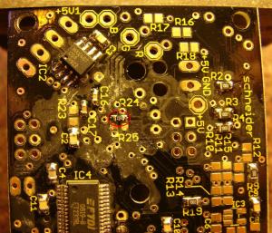
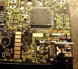
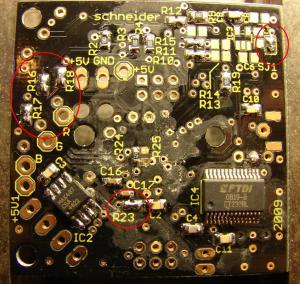
The current pcb requires some solder bridges at R10, R11, R12, R16, R17, R18, R23 and SJ1. They are located at the bottom of the pcb. Short them using solder:
TODO: add mark in image for r10,r11,r12
Step 4.4:
Parts used: 2 x 2×3 header(ISP, JP2), 1 x 8 Ohm resistor(R7), 2 x 5 Ohm resistor(R5, R6), 1 x screw terminal(X1), 1x 1×4 header(X2), 1x 1×2 header (USBPWR)
Solder the resistors on top of each other as shown in the picture.
To solder the connectors put them into their holes, put the pcb onto a flat surface upside down and solder one pin. Check that the connector is in correct position and solder the other pins.
Step 4.5:
Parts used: 1 x 3 Pin Molex type connector
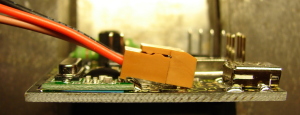
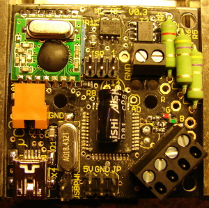
Take care that the rf module does not block the connector. To prevent this mount the connector in an assembled state as shown in the picture:
Step 4.6:
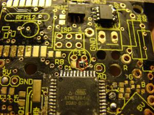
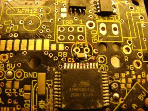
Parts used: 1 x 100 uF electrolyte capacitor(C14)
This capacitor has a polarity! The negative side is marked by a white stripe on one side. This side has to point to the rf module. If you bend the leads to 90 degrees you can lay the capacitor onto the big chip:
The pcb is now finished!
Step 5: Power supply
As most 5V wall plugs come with a different connector we'll add our own 2.5mm dc jack to them to keep compatibility. If your wall plug already has 2,1mm you can skip the next step and continue at 5.3 so the 2.5mm dc connector is unused.
If possible use a bigger solder tip for this. A 2mm tip is fine.
Step 5.1:
Step 5.1:
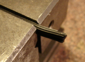
The rippled wire is usually the negative side of the power supply. If unsure use a voltmeter to verify this!
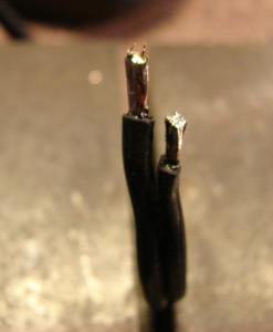
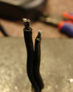
Cut the negative side about 5mm shorter than the positive side, strip some insulation, add solder and cut the leads to about 5mm:
Step 5.2:
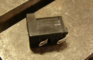
Parts used: 1 x 2.5mm dc connector
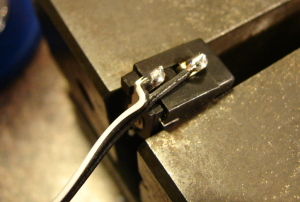
Put the connector into the vice and add solder to the terminals. Make sure the solder sticks to the leads. You have to heat the bigger one longer to make it hot enough:
Step 5.2:
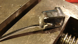
Don't forget to put the casing onto the cable before soldering the connector
Solder the cable onto the connector with the shorter wire connecting to the larger lead:
Step 5.3:
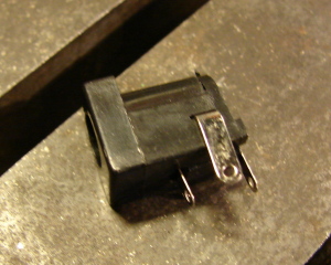
Parts used: 2.5mm dc jack
Remove the lead on the side of the connector and bend the remaining two to the front:
Step 5.4:
Parts used: 10cm twin wire
Strip some insulation from the twin wire, add solder to the copper and solder them to the dc jack. Solder the marked wire to the lead at the back of the connector. This is the positive side of the connector
Step 5.5:
Step 6: Infrared receiver
This step is different depending on the revisions of your kit.
Kit Revision 2: Step 6.2:
Parts used: 4.8mm, 2.4mm heat-shrink tube, IR receiver, 3 pin Molex type connector
Connect the ir receiver as shown to the cable. Use the 2.4mm heat-shrink tube to insulate the leads and the 4.8mm heat-shrink tube to hold the wires together:
Kit Revision 3: Step 6.3:
Parts used: 4.8mm, 2.4mm heat-shrink tube, IR receiver, 3 pin Molex type connector, 100 Ohm resistor, 47 uF capacitor
This kit contains a SFH5110-36 as infrared receiver. This receiver requires some extra components and a different connection.
Step 6.3.1:
Step 6.3.2:
Add the capacitor and the resistor as shown in the picture. Make sure the negative side of the capacitor is connected the the middle pin.
Step 6.3.3:
Cut the cable of the connector as shown in the the next picture, remove the isolation and add solder to the ends:
Step 6.3.4:
Add heat shrinking tube as shown in the picture and solder the wires as shown in the second picture to the IR receiver.
Step 6.3.5:
Shrink the heat shrinking tube.
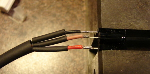
Kit Revision 4 (EH2010): Step 6.4:
Parts used: 4.8mm, 2.4mm heat-shrink tube, IR receiver, 3 pin Molex type connector
|-------|
|       |
|  /-\  |
|  \-/  |
|       |
---------
 |  |  |
 |r |b |b
 |e |l |r
 |d |k |o
 |  |  |
Connect the ir receiver as shown to the cable. Use the 2.4mm heat-shrink tube to insulate the leads and the 4.8mm heat-shrink tube to hold the wires together:
Step 7: Antenna
Parts used: antenna wire
Antenna length: λ / 4 = c / 4f = (300*10^6 ms) / (433 MHz * 4) = 17,3 cm
Solder the antenna to the antenna pad under the ir connector:
Step 8: Led
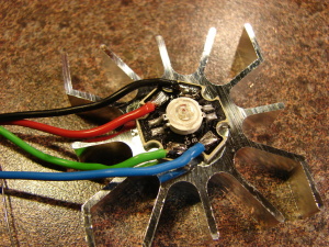
Parts used: rgb led, red, green, blue and black wire
The led comes mounted on a heat sink. This makes soldering the leads of the led more difficult. Use a bigger tip and a strong soldering iron to heat the pads fast enough.
Solder the four wires as shown to the led:
Step 9: Final assembly
Step 9.1:
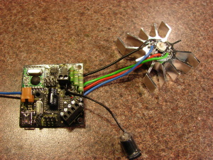
Solder the four wires of the led to their corresponding connections on the pcb. The red, green and blue wires go to the pads marked R, G and B. The black wire goes to the hole which is marked with +5V at the bottom side. It's near the screw terminal.
Strip some insulation from the twin wire coming from the dc jack and add some solder. Put the wires into the screw terminal and tighten it. The marked wire goes to the terminal near the big resistors:
Take a look at Test 1: short circuit before you connect your moodlamp to the power supply.
It's now time to have a look at Voraussetzungen

