The luftschleuse2 project allows you to simulate a complete luftschleuse2 system on your computer. The simulation utilizes the same code base as a real luftschleuse2 system.
lockd
The lockd daemon is supplied with a special configuration file: lockd-udp.cfg
It starts up lockd with two configured doors and expects the Master Controller to communicate with lockd via UDP. Expected RX sequence numbers are taken and stored in two temporary files. If your system does not have a /tmp directory, you should change the path to these files in the configuration file. The configuration file mimics the setup of luftschleuse2 at the muccc. The Master Controller has three buttons (DOWN, CLOSED, MEMBER), one switch (PUBLIC), three LEDs (DOWN, CLOSED, MEMBER) and an LCD to display status information.
The syslog output is directed to localhost on port 23514. You can use the syslog-receiver.py without any options to capture the syslog output.
Master Controller
Physical Master controllers run on a small 8-Bit micro controller. To run the code for the Master Controller, abstractions have to be introduces to simulate the hardware attached to this micro controller. The Master Controller simulation takes the C source code of the Master Controller and adds virtual peripherals. It simulates the LCD, shows the state of the LEDs, takes input from the keyboard to simulate button presses, simulates serial communication with the Master via unicast UDP and simulates the communication with other bus devices (Lock COntrollers) via multicast UDP.
To compile the Master Controller simulation, go to the software/mastercontroller_simulation directory and run make:
cd software/mastercontroller_simulation
make clean # Do not omit this line as the Master Controller can share object files with the Lock Controllers
make
To successfully build the Master Controller simulation you need to have the development libraries for openssl, ncurses and SDL installed (libssl-dev, libncurses5-dev and libsdl1.2-dev on Debian/Ubuntu).
The makefile takes the source code from software/mastercontroller and compiles it together with the simulated hardware in software/mastercontroller_simulation. The resulting binary is named mastercontroller_simulator. You can now start the Master Controller:
./mastercontroller_simulator
It creates a window with the simulated LCD and shows the state of the user interface inside the console window:
X DOWN    Press 'D' to toggle the DOWN button.
  CLOSED  Press 'C' to toggle the CLOSED button.
  MEMBER  Press 'M' to toggle the MEMBER button.

          Press 'P' to toggle the PUBLIC switch.
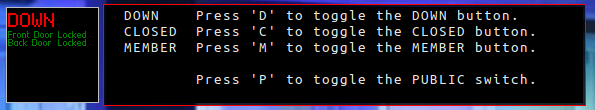
You might have to resize the window of the simulated LCD to see it completely.
Press one of the mentioned keys to press a button or toggle the switch. Do not forget to release the button again.
The system simulates the Master Controller of our system at the muccc. Change the contents of cli.c to change the appearance of the user interface. You can relabel the buttons and the LEDs. If you want to have more LEDs or buttons, you also have to change the source code of the Master Controller under src/mastercontroller.
Lock Controller
As the Master Controller, the Lock Controller also need simulated hardware to be simulated. The most complex piece of hardware is the actual lock. To not have to create a command line interface for each type of lock, the Lock Controller simulation replaces the driver for the locks with a dummy driver and lets the user view the input from the system to this driver and lets the user directly manipulate the output of the driver (which currently consists of 7 status flags).
The code simulation the Lock Controllers is located at software/lockcontroller_simulation. Do not run the Makefile from this directory directly.
To build a lock controller you have to supply the code with an encryption key and the name of the door. software/front-door_simulation and software/front-door_simulation contain configurations for two example doors. These doors are also in the luftschleuse2 system of the muccc. They are preconfigured in the example configuration of lockd mentioned above.
Go to one of the directories mentioned above and enter:
make clean # Do not omit this line as the Lock Controllers share object files between each other.
make
Always run make clean to not create corrupted executables
You can now start a simulated Lock Controller:
./lockcontroller_simulator
A simulated Lock Controller gets launched: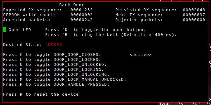
Press one of the key to toggle a signal from the driver or press the button on the door.
Press 'B' to ring the bell. If you ring the bell for longer than 400 ms and the system is in the 'MEMBER' state, you can watch the door getting unlocked for a few seconds. (The bell code can be changed to a more complex sequence in bell_process.c of the Lock Controller)
Press 'R' to reset the device, without loosing the contents of the simulated EEPROM.
Communication
All communication between the different system components is done trough UDP. The following ports and IPs are used:
localhost:31000 - lockd listens for data from the Master Controller
localhost:32000 - The Master Controller waits for data from lockd
239.0.0.1:6000 - Multicast address which is used by the Lock Controllers and the Master Controller
The multicast address is used to simulate the multi-drop RS485 bus between the different devices. As devices turn off their receiver while transmitting, they do not accept their own packets they send to the multicast group.